
Skip to content
Shandong Hardford Mtec Co., Ltd
Get a quote

GMB1813

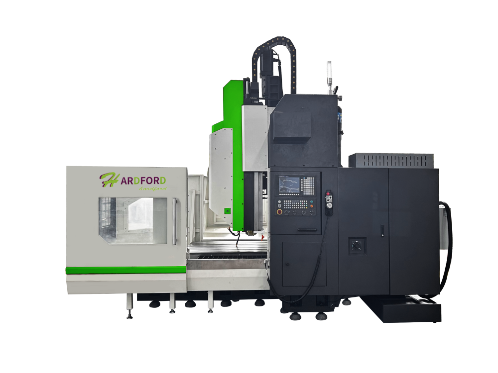
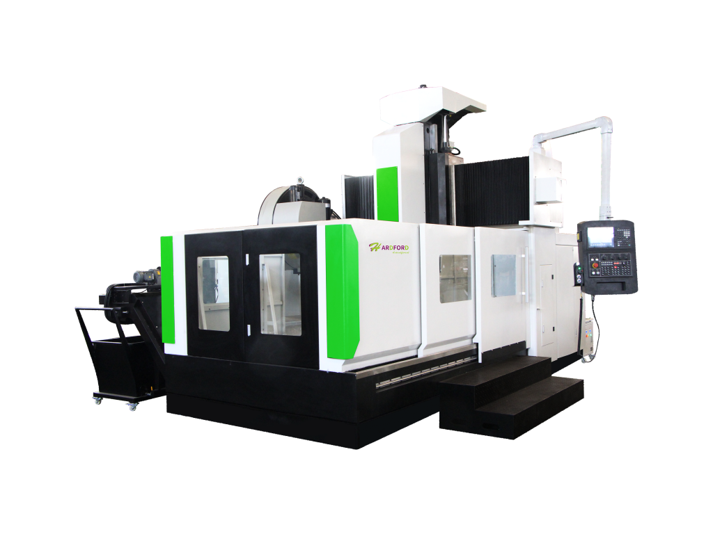
Gantry machining center

The GM series CNC gantry machining center features a reinforced bed structure and a rationally designed symmetrical layout, resulting in high rigidity and stability. It offers multiple machining functions including milling, boring, drilling (reaming, boring), and tapping, and is widely used in various machining fields such as automotive, mold making, aerospace, packaging, and hardware.

Get a quote Request the brochure

Product photo gallery

Product description

52

Selling points

  • .Overall Structural Design
  • This CNC gantry machining center adopts a fixed gantry and moving worktable structure, delivering superior structural stability and consistent machining accuracy. The complete machine assembly consists of a heavy-duty worktable, integral cast bed, rigid columns, high-stiffness crossbeam, precision sliding saddle, as well as standardized hydraulic, lubrication, cooling and filtration systems, automatic chip removal device, rotating control panel and full electrical control system. The integrated layout ensures reliable performance, convenient operation and easy daily maintenance.
  • .X-Axis (Bed & Worktable System)
  • Both the machine bed and worktable are integrally cast from high-strength cast iron with resin sand molding technology, featuring excellent rigidity, vibration resistance and structural stability. The X-axis adopts a heavy-duty guide rail support structure, with high-load sliders scientifically arranged on roller linear guides based on mechanical optimization principles. This design greatly enhances overall load-bearing capacity and guarantees long-term stable precision even under continuous heavy-load operation.
  • The X-axis transmission system is driven by an AC servo motor paired with a heavy-duty precision ball screw, realizing stable linear reciprocating movement. The screw adopts fixed pre-tensioned support at both ends, effectively eliminating thermal deformation and improving positioning accuracy and repeatability.
  • .High-Rigidity Cast Column & Crossbeam
  • The main column and crossbeam are manufactured from high-strength cast iron via resin sand precision casting. The integral thick-wall casting structure effectively reduces cutting vibration and improves overall structural rigidity, providing a solid foundation for heavy-duty milling and high-precision machining.
  • .Y-Axis (Saddle System)
  • The saddle is made of high-strength cast iron for enhanced durability and structural rigidity. The Y-axis crossbeam is designed with an optimized dense reinforcing rib layout, delivering outstanding stiffness, excellent dynamic performance and superior precision retention. It supports long-term full-load and low-speed stable operation without accuracy deviation.
  • Equipped with an AC servo motor and precision ball screw transmission, the Y-axis achieves smooth, sensitive and accurate linear reciprocating motion, ensuring stable feeding performance during complex machining processes.
  • .Z-Axis Nitrogen Balance System
  • The Z-axis adopts a mature dual-rod nitrogen balance cylinder structure. Featuring a simple, stable and easy-to-maintain design, it ensures balanced spindle operation, smooth vertical movement and consistent cutting stability during long-cycle machining.

Specifications

Name Unit GMC1613 GMC1813 GMC2016 GMC2518
staging Table size mm 1600*1000 2000*1000 2000*1300 2500*1600
Bearing capacity of workbench Kg 2000 3000 4000 7000
T-type groove width mm 7*22*140 7-140*22 7-170*22 9-180*22
range of work X axis travel mm 1600 2000 2000 2500
Y axis travel mm 1300 1300 1650 1800
Z axis travel mm 800 800 800 1000
Distance from spindle end face to mm 190-990 190-990 250-1050 150-1150
workbench
longmen too wide mm 1300 1300 1660 1800
principal axis Taper hole model BT40 BT50 BT50/φ190 BT50/φ190
Pull nail specification P40T-1-MAS403(45°) P50T-1-MAS403(45°) P50T-1-MAS403(45°) 10-6000
range of speeds rpm 10-8000 10-8000 10-6000
tool ATC T 24 24 24 24
FEED Cut into the feed speed range m/min 1-10. 1-10. 1-10. 1-7.
X-axis fast movement m/min 18 15 15 15
Y-axis rapid movement m/min 18 15 15 15
Z-axis rapid movement m/min 12 15 15 10
system configuration FANUC
Motor X-axis motor Nm 11 20 20 30
configuration Y-axis motor Nm 11 20 20 20
Z-axis motor Nm 11 20 20 20
Spindle motor Kw 11--15 15-18.5 15-18.5 22
Drive configuration guide rail specification (XYZ) X 45 45 55 55
Y 45 55 55 55
Z box box box box
screw specification (XYZ) X 5012 6312 6312 6312
Y 5012 5010 5010 5010
Z 5012 5010 5010 5010

Request a quotation

We usually reply within 1 business day.

Other models in this series


Questions? Chat with us →